The pioneer of all industrial communications protocol is Modbus, which is still widely used in industry and IoT as well.
Modbus has been created in 1979 by Modicon (now Schneider Electric). The protocol is now an open-source protocol allowing communication between industrial devices (controllers, sensors, actuators, HMI, etc.) of various manufacturers. It operates under the Single-Master model.
Modbus works over different bus types with high reliability in data transmission and requires very little memory and processing power, making it perfect for implementing in a microcontroller.
Modbus protocol is very flexible regarding the physical and data link layers. For exemple :
- Modbus TCP/IP: It uses Ethernet as the physical layer and TCP/IP protocols for data transmission. It’s based on the client/server model.
- Modbus over Serial (RS-485/RS-422 or RS-232): It uses a serial port and works using the master/slave model. There’re two sub-types:
- Modbus RTU (Remote Terminal Unit): The data sent are in Hexadecimal format.
- Modbus ASCII: The data sent are in ASCII format.
- Modbus LoRa: The date are transmitted serially and wirelessly using Lora protocol.
- Modbus Plus: HDLC is used as the data link layer, allowing data transmission up to 1Mbps.
The Single-Master Model
Modbus works on a Single-Master Model, which means that a single Master (as a TPC/IP Client) can speak to several Slaves (as TPC/IP Servers). The master requests and sends information to its slaves individually. Each one has a unique identifier: a Slave number in the Modbus over Serial mode and IP address in the Modbus TCP/IP mode.
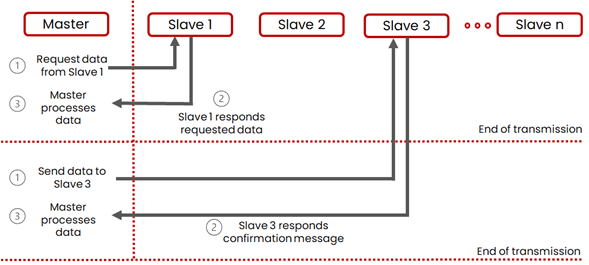
The Master requests information from one of its Slaves, and that Slave is the only one that responds. Then, for example, the Master writes data to another Slave, and only that one receives it.
If the Slave cannot process the data, it’ll respond with an error code.
Each Slave requires memory to store the data that the Master requests or sends. Each location is called a “Register” and is a variable of two bytes in length. It will have write or read properties (or both). It’s the manufacturer of the device who defines the quantity and layout of memory depending on the application.
There are four categories of storable date : Discrete Inputs (one bit in Read-Only mode), Coils (one bit in Read-Write mode), Input Registers (16-bit word in Read-Only mode) and Holding Registers (16-bit word in Read-Write mode).
The data are sent into messages called PDU (Protocol Data Unit) composed of a Function Code (action to execute, acknowledge of excused function or error message) and Data (depends of Function Code).
Depending to the communication mode (TCP-IP, over Serial, etc…), PDU is transmitted differently using ADUs (Additional Data Unit). For extensive information, please check there.
At Voltanode, we can help you implementing Modbus into your design.