Balanced and Unbalanced Audio Interfaces
Balanced and unbalanced refer to two different types of audio interconnections commonly used in audio systems. The terms relate to the impedances of the signal conductors with respect to ground. Understanding the differences between balanced and unbalanced interfaces, and best practices for interconnecting balanced and unbalanced equipment, is important for achieving optimal audio performance and minimizing noise issues.
Unbalanced Interfaces
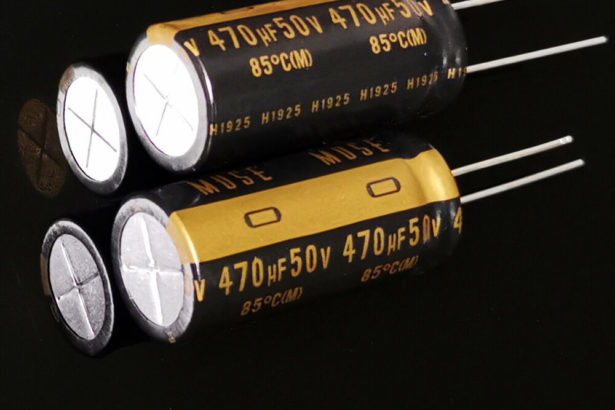
An unbalanced interface connects one signal conductor to ground and has a non-zero impedance on the other signal conductor. The shield serves as both a signal conductor and a path for ground currents. Typical unbalanced input impedances range from 10kΩ to 100kΩ. Typical unbalanced output source impedances range from 330Ω to 1kΩ with 4.7μF to 47μF coupling capacitors for consumer equipment, and 47Ω to 220Ω with 47μF to 220μF capacitors for semi-pro equipment.
The main disadvantage of unbalanced interfaces is that ground noise currents flowing in the cable shield add directly to the signal, causing audible hum and buzz. The shared impedance of the signal and ground return is what enables this interference coupling.
Balanced Interfaces
A balanced interface uses two signal conductors that have equal impedances to ground. A differential input amplifier is used to reject common-mode ground noise that is identical on both conductors.
The most common balanced input circuit uses a matched resistor network to achieve high common-mode rejection ratio (CMRR). However, its noise rejection is very sensitive to any impedance imbalances in the driving source. Typical balanced output circuits provide equal, opposite polarity signals (signal symmetry) with matched source impedances. Contrary to popular belief, signal symmetry does not affect noise rejection – only the matching of the source impedances matters.
Interconnecting Unbalanced and Balanced
There are several options for interfacing unbalanced equipment to balanced inputs:
- A simple adapter cable connects the unbalanced output across the balanced input. This relies on the differential input rejecting ground noise, but provides limited performance (around 30 dB rejection) due to the source impedance imbalance.
- An output transformer can be used to improve the source impedance balance seen by the balanced input. This provides moderate ground noise rejection (around 55 dB) at low frequencies but degrades at high frequencies due to transformer capacitance.
- An input transformer is the best option, effectively replacing the active balanced input stage. By having very high common-mode input impedance, the transformer provides excellent ground noise rejection (100 dB or more) across the audio band, even with unbalanced sources.
- Unbalanced outputs can be converted to balanced by adding an impedance-matched network to ground to create the inverted output signal. With proper component choices, this provides a true balanced output with good impedance matching.
For connecting balanced outputs to unbalanced inputs:
- An output transformer and “pad” built into a cable can provide moderate ground noise rejection (60 dB) for low frequencies, with some attenuation to match levels. High frequency rejection is limited by transformer capacitance imbalance.
- A 4:1 step-down transformer is the optimal solution, providing 12 dB of attenuation, very high ground noise rejection across the audio band, galvanic isolation, and minimal loading of the balanced line.
Other Considerations
When making unbalanced connections, it is very important to minimize any resistance in the shield/ground path that is shared with the signal. Using high quality connectors and connecting the cable shield directly to the chassis ground point helps bypass any remaining shared resistance.
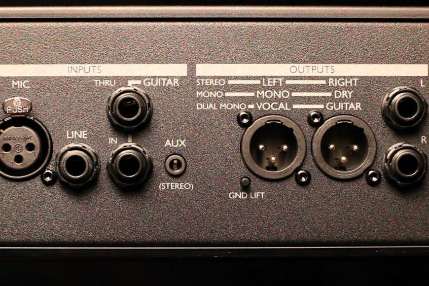
The cable shield connection at balanced inputs is a tradeoff. Connecting pin 1 directly to chassis is the most common practice and is generally recommended for unbalanced consumer gear to avoid excessive common-mode voltages. However, in high-end balanced systems, pin 1 “ground lift” switches can sometimes improve noise performance and avoid potential oscillation or crosstalk, except on microphone inputs which require a ground path.
In summary, for best performance when interconnecting balanced and unbalanced equipment, use input transformers or impedance-matching networks to provide optimal impedance matching and ground isolation. Active balanced input stages are highly sensitive to source impedance imbalances that degrade their noise rejection. Simple adapter cables provide minimal benefit. With proper interfacing, balanced interconnections can provide extremely high ground noise rejection and performance in real-world audio systems.
Some further readings :